看看这个有源箝位电路图,如何把效率提高到85%以上,本电源有一定难度
这是几个月前没有搞定的一个项目,现在又要开始做了.技术参数如下
输入直流11-16伏,输出dc20v,16v,15v可以调节,功率100瓦,
电源尺寸12.5mm*55mm*35mm
效率大于85%,频率300k,原副边隔离
各位,我自己功底有限,以前开始做时便用了有源箝位,使用2:8的变压器升压,但正是这一原因导致效率底下,请各位就本图或合理的方案提提看法,致谢!1065602999.doc
看看这个有源箝位电路图,如何把效率提高到85%以上,本电源有一定难度
全部回复(22)
正序查看
倒序查看
现在还没有回复呢,说说你的想法
Topology
I thought you don\'t need to used active clamper circuit, because if you used self driver circuit, the improvement is poor. I had designed 2 90W adapter, one is used isolated flyback converter, input 9V~16V dc, output is selectable from 15V to 20Vdc, the minimum efficiency is 80%@11V dc, another is used SEPIC converter, input is 9V~28V dc, dual outputs, one is selectable from 5Vdc to 24Vdc @ 4.75A maximum, one is 3V~9V @ 1A maximum, the minimum effciency is higher than 88% under 9V dc in, 19Vdc out @90W load. So you can try SEPIC circuit, it is simply and easy to acheive ZVS function by use a aux. mosfet.
I thought you don\'t need to used active clamper circuit, because if you used self driver circuit, the improvement is poor. I had designed 2 90W adapter, one is used isolated flyback converter, input 9V~16V dc, output is selectable from 15V to 20Vdc, the minimum efficiency is 80%@11V dc, another is used SEPIC converter, input is 9V~28V dc, dual outputs, one is selectable from 5Vdc to 24Vdc @ 4.75A maximum, one is 3V~9V @ 1A maximum, the minimum effciency is higher than 88% under 9V dc in, 19Vdc out @90W load. So you can try SEPIC circuit, it is simply and easy to acheive ZVS function by use a aux. mosfet.
0
回复
提示
@arthur.deng
TopologyIthoughtyoudon\'tneedtousedactiveclampercircuit,becauseifyouusedselfdrivercircuit,theimprovementispoor.Ihaddesigned290Wadapter,oneisusedisolatedflybackconverter,input9V~16Vdc,outputisselectablefrom15Vto20Vdc,theminimumefficiencyis80%@11Vdc,anotherisusedSEPICconverter,inputis9V~28Vdc,dualoutputs,oneisselectablefrom5Vdcto24Vdc@4.75Amaximum,oneis3V~9V@1Amaximum,theminimumeffciencyishigherthan88%under9Vdcin,19Vdcout@90Wload.SoyoucantrySEPICcircuit,itissimplyandeasytoacheiveZVSfunctionbyuseaaux.mosfet.
非常感谢您的关注和建设性方案,我的电路要求原副边隔离,sepic电路没有接触过,我会去进行了解和
学习的,对于反激方案,主要可以少一个大电感,有助减小体积,您的功率为290瓦,应是90瓦吧?估计您用的是同步整流法,要不效率不大可能达到80%.
sepic方案不知道您用的什么整流方式,提个非常过份的要求,您能把大体的原理图发给我吗?
我的email:chenqq2000@sohu.com
学习的,对于反激方案,主要可以少一个大电感,有助减小体积,您的功率为290瓦,应是90瓦吧?估计您用的是同步整流法,要不效率不大可能达到80%.
sepic方案不知道您用的什么整流方式,提个非常过份的要求,您能把大体的原理图发给我吗?
我的email:chenqq2000@sohu.com
0
回复
提示
tu
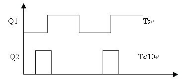
各位,如何才能实现下叙时序控制?
 500) {this.resized=true; this.width=500; this.alt='这是一张缩略图,点击可放大。\n按住CTRL,滚动鼠标滚轮可自由缩放';this.style.cursor='hand'}" onclick="if(!this.resized) {return true;} else {window.open('http://u.dianyuan.com/bbs/u/0/1065842127.gif');}" onmousewheel="return imgzoom(this);">
各位,如何才能实现下叙时序控制?
 500) {this.resized=true; this.width=500; this.alt='这是一张缩略图,点击可放大。\n按住CTRL,滚动鼠标滚轮可自由缩放';this.style.cursor='hand'}" onclick="if(!this.resized) {return true;} else {window.open('http://u.dianyuan.com/bbs/u/0/1065842127.gif');}" onmousewheel="return imgzoom(this);">
 0
回复
提示
@chenqq2000
非常感谢您的关注和建设性方案,我的电路要求原副边隔离,sepic电路没有接触过,我会去进行了解和学习的,对于反激方案,主要可以少一个大电感,有助减小体积,您的功率为290瓦,应是90瓦吧?估计您用的是同步整流法,要不效率不大可能达到80%. sepic方案不知道您用的什么整流方式,提个非常过份的要求,您能把大体的原理图发给我吗?我的email:chenqq2000@sohu.com
For your question
My means that I design two 90W adapter. Used flyback, I didn\\\\\\\'t use SR, just by diode, and also is islated between primary and secondary.For the SEPIC circuit, you can get it in TI web-site. I only can provide you some tips and some experience, because there have been patented limit by our company, and I suggest you use current mode controller ex uc3843, because it is easy to design the control loop and current limit or short protection. If you have any question you can feel free to contact me. 1065780688.pdf
My means that I design two 90W adapter. Used flyback, I didn\\\\\\\'t use SR, just by diode, and also is islated between primary and secondary.For the SEPIC circuit, you can get it in TI web-site. I only can provide you some tips and some experience, because there have been patented limit by our company, and I suggest you use current mode controller ex uc3843, because it is easy to design the control loop and current limit or short protection. If you have any question you can feel free to contact me. 1065780688.pdf
0
回复
提示
@chenqq2000
回鹅兄:如果效率能够达到85%,散热不是问题,非对称半桥我认为用在这里不太合适,电压要求可调节,原边电流有大,所以我认为不太好.sepic结构不知道可以用些什么ic?
controller
SEPIC is easy to control, general control IC all can be available, TL494 and UC384x etc. but TL494, the switching speed is lower, but for your application, should be no any problem.
SEPIC is easy to control, general control IC all can be available, TL494 and UC384x etc. but TL494, the switching speed is lower, but for your application, should be no any problem.
0
回复
提示
@arthur.deng
controllerSEPICiseasytocontrol,generalcontrolICallcanbeavailable,TL494andUC384xetc.butTL494,theswitchingspeedislower,butforyourapplication,shouldbenoanyproblem.
authur:
我先用硬开关做了试验,效率只有72%,所以要提高到85%,必须实现软开关,若用3843,辅助管的时序怎么实现,一般把这个辅助信号设为Ts/10,如下边图所示,但怎样从3843获得这样的辅助驱动波形呢?你能告诉相关的方法吗?
我先用硬开关做了试验,效率只有72%,所以要提高到85%,必须实现软开关,若用3843,辅助管的时序怎么实现,一般把这个辅助信号设为Ts/10,如下边图所示,但怎样从3843获得这样的辅助驱动波形呢?你能告诉相关的方法吗?
0
回复
提示
@chenqq2000
authur:我先用硬开关做了试验,效率只有72%,所以要提高到85%,必须实现软开关,若用3843,辅助管的时序怎么实现,一般把这个辅助信号设为Ts/10,如下边图所示,但怎样从3843获得这样的辅助驱动波形呢?你能告诉相关的方法吗?
efficiency
As you side, I thought your transformer design should not be optimized, based on my experience, the efficiency can achieve 80% if used general flyback topology, if used SEPIC, the efficiency should be improved to higher, ZVS can used self-driver circuit(just a suggestion, I didn\'t try it), by the way, the size is L*W*H is ?
As you side, I thought your transformer design should not be optimized, based on my experience, the efficiency can achieve 80% if used general flyback topology, if used SEPIC, the efficiency should be improved to higher, ZVS can used self-driver circuit(just a suggestion, I didn\'t try it), by the way, the size is L*W*H is ?
0
回复
提示
@arthur.deng
efficiencyAsyouside,Ithoughtyourtransformerdesignshouldnotbeoptimized,basedonmyexperience,theefficiencycanachieve80%ifusedgeneralflybacktopology,ifusedSEPIC,theefficiencyshouldbeimprovedtohigher,ZVScanusedself-drivercircuit(justasuggestion,Ididn\'ttryit),bytheway,thesizeisL*W*His?
是的,尺寸正是这个L*W*H=12.5*55*35
SEPIC的ZVS自驱动你没有用过,不知道你做的90WSEPIC如何实现效率88%的,你做的尺寸能告诉我是多少吗?
SEPIC的ZVS自驱动你没有用过,不知道你做的90WSEPIC如何实现效率88%的,你做的尺寸能告诉我是多少吗?
0
回复
提示
@arthur.deng
efficiencyAsyouside,Ithoughtyourtransformerdesignshouldnotbeoptimized,basedonmyexperience,theefficiencycanachieve80%ifusedgeneralflybacktopology,ifusedSEPIC,theefficiencyshouldbeimprovedtohigher,ZVScanusedself-drivercircuit(justasuggestion,Ididn\'ttryit),bytheway,thesizeisL*W*His?
~{;X84~};
sepic~{5gB72\"2;:CSC#,5%JGR;8v~}mos~{5D9X6OS&A&>MBi73!#~}
sepic~{5gB72\"2;:CSC#,5%JGR;8v~}mos~{5D9X6OS&A&>MBi73!#~}
0
回复
提示

