Output power:120W
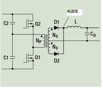
Topolodge:Half Bridge
PWM Controller:UC2825
Operation mode:Voltage or Current Mode
Output:Multi output,5V/2A,24V/2A.....
Feedback regulation:5V
Duty Cycle:80%
Switch frequency:100KHz
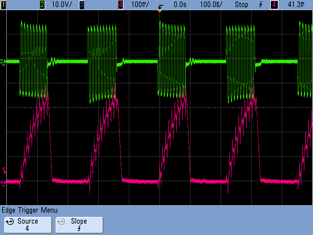
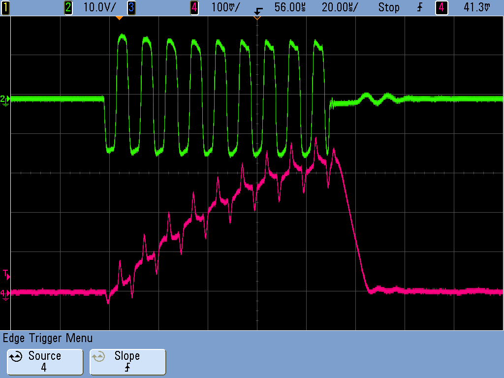
测试的波形是在电压模式下测试的,Channel 2为下管Q1的GS波形,Channel 4为输出滤波电感的电流波形,使用电流钳测试的,电流钳加在电感的前端,即整流二极管和滤波电感相连接的那一点.
50981231055339.pdf UC2825 Datasheet
 500) {this.resized=true; this.width=500; this.alt='这是一张缩略图,点击可放大。\n按住CTRL,滚动鼠标滚轮可自由缩放';this.style.cursor='hand'}" onclick="if(!this.resized) {return true;} else {window.open('http://u.dianyuan.com/bbs/u/73/50981231055415.gif');}" onmousewheel="return imgzoom(this);">
测试波形1
 500) {this.resized=true; this.width=500; this.alt='这是一张缩略图,点击可放大。\n按住CTRL,滚动鼠标滚轮可自由缩放';this.style.cursor='hand'}" onclick="if(!this.resized) {return true;} else {window.open('http://u.dianyuan.com/bbs/u/73/50981231055479.gif');}" onmousewheel="return imgzoom(this);">
测试波形2
 500) {this.resized=true; this.width=500; this.alt='这是一张缩略图,点击可放大。\n按住CTRL,滚动鼠标滚轮可自由缩放';this.style.cursor='hand'}" onclick="if(!this.resized) {return true;} else {window.open('http://u.dianyuan.com/bbs/u/73/50981231058333.gif');}" onmousewheel="return imgzoom(this);">
拓扑结构

