• 回复
  • 收藏
  • 点赞
  • 分享
  • 发新帖

请版主进来帮忙指导一下——基于L6562A的42W单级PFC恒压电源的saber仿真


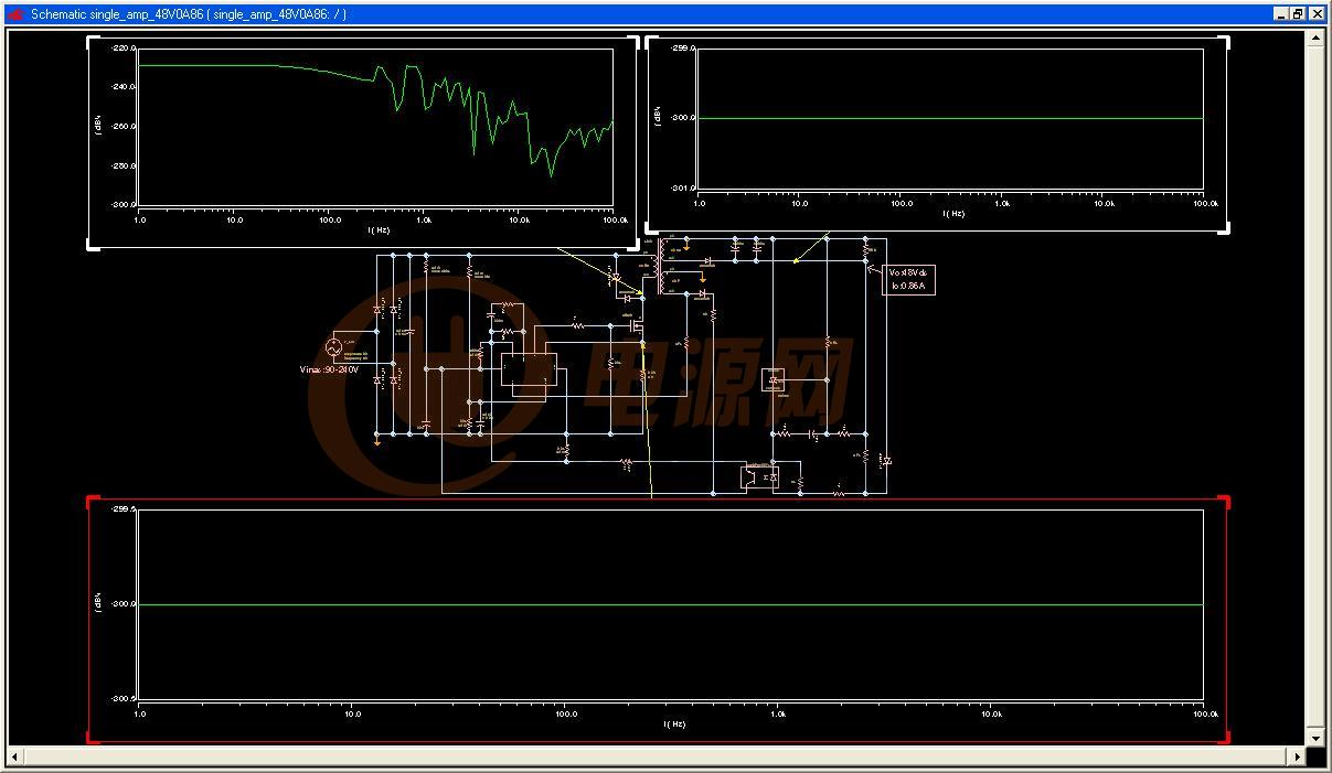
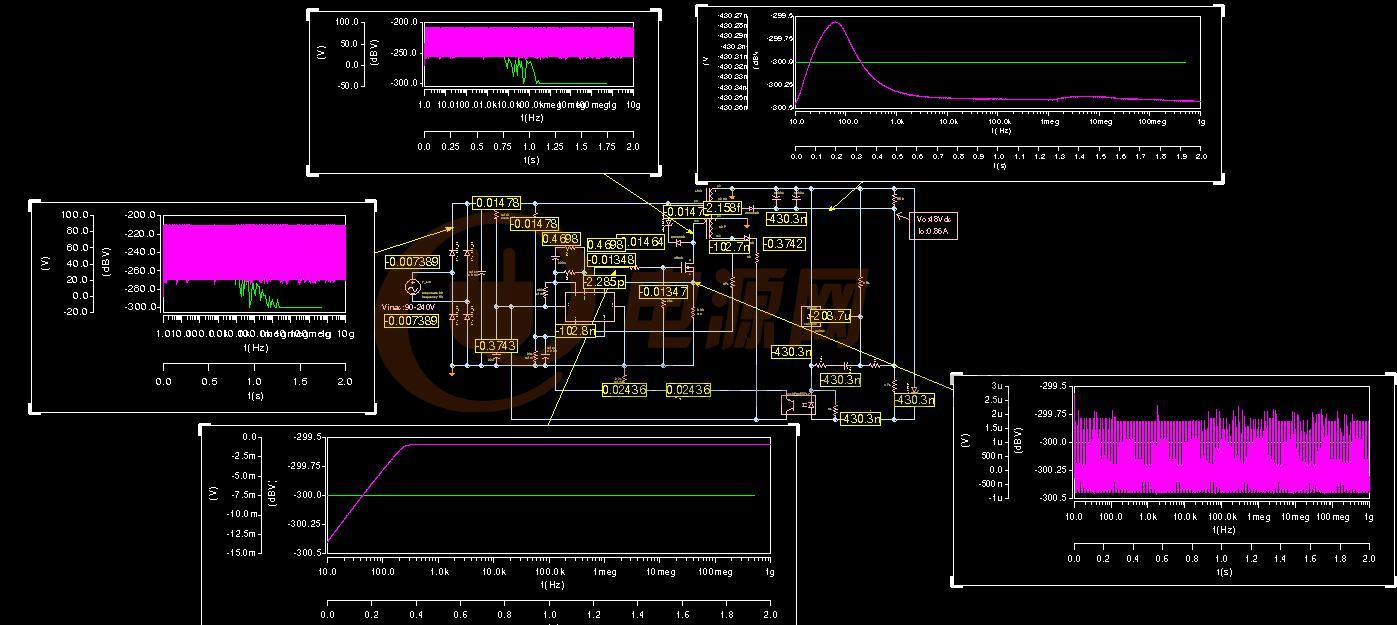
如图,输入电压范围为90-240Vac,输出48V0.86A,不知道仿真时怎么设置,请老师们赐教下。谢谢

用saber2006做的电路仿真文件:single_amp_48V0A86 

生成网表时报错:


第一个警告解决了,就是把输出电源那里的“amplitude"参数填上就好了,如图


还有两个告警,就是提示某端的单位属性定义成了“电气”某端定义成了“磁”,由于这个电路是用别人的改过来的,所以,到现在为止还没有找到这两个端口在哪里,怎么定义她们的单位属性。

这个电路里的变压器参数不知该怎样填!在此写出来让大师们指导一下

其中有初级电流,电感,耦合系数,内阻等等参数,不知哪些是必须填哪些可以不用填?!初级电流是用计算的峰值电流还是平均电流呢?谢大师们不吝赐教。

这是变压器的属性框


下面是属性框里各行功能的解释

#VERSION

#DATED 11-Nov-2004.14:47:36
# encrypted template xfrl3 p1 m1 p2 m2 p3 m3 = l1, l2, l3,
#     n1, n2, n3, ur, len, area,
#     k12, k13, k23, r1, r2, r3
#***********************************************************************
# Linear transformer  (called by: xfrl3 )                          #
#                                                                                #
#                                                                                 #
#                      flux -->                                                 #
#       First coil   _______________ Second coil                #
#                   |                        |                                   #
#               *  |                        |     *                             #
#I1 --> + o---===                  ===----o +   <-- I2           #
#     V1           \  N1             N2   /               V2                 #
#                    \                         /                                   #
#  <--   - o---=|=                    =|=----o -   -->                 #
#                    |                         |                                   #
#                    |                         |      *                           #
#                    |                      ===----o   +   <-- I3          #
#                    |                  N3   /           V3                     #
#                    |                         /                                   #
#                    |                       =|=----o   -   -->              #
#                    |                         |                                   #
#                    |                         | Third coil                     #
#                    -------------------------                                #
#                      <-- flux                                        #
#                                                                      #
#       NOTE: 1. The above diagram is informal and does not represent  #
#                the details of magnetic path in the modeled device.   #
#             2. Note the orientation of windings indicated by the     #
#                slashes and winding terminals "over" and "under" the  #
#                core.                                                 #
#                                                                      #
#                      area = cross section area of flux path          #
#                      len = length of flux path                       #
#                       ur = permeability of core wrt free space       #
#                       k  = coefficient of coupling between coils     #
#                                                                      #
#                                                                      #
#***********************************************************************
#                                                                      #
#       Note:  The inductances can be specified with the single        #
#       parameters l1, l2, and l3, or by the magnetic parameters       #
#       l, a, ur, and (n1, n2, or n3).                                 #
#       If l1, l2, or l3 are specified, the other parameters           #
#       are not used.                                                  #
#                                                                      #
#**********************************************************************#
#                     Copyright 2004 Synopsys Inc.                     #
#          This template and the associated documentation are          #
#             confidential and proprietary to Synopsys, Inc.           #   
#        Your use or disclosure of this template is subject to         #
#       the terms and conditions of a written license agreement        #
#           between you, or your company, and Synopsys, Inc            #
#**********************************************************************#
encrypted template xfrl3 p1 m1 p2 m2 p3 m3 = l1, l2, l3,
    n1, n2, n3, ur, len, area,
    k12, k13, k23, r1, r2, r3
electrical  p1, # First winding positive node.
  m1, # First winding negative node.
  p2,  # Second winding positive node.
  m2, # Second winding negative node.
  p3,  # Third winding positive node.
  m3 # Third winding negative node.
# Electrical specification for inductances.
number l1=undef, # First winding inductance.
 l2=undef, # Second winding inductance.
 l3=undef # Third winding inductance.
# Magnetic specification for determining inductances.
number  n1=undef, # Number of turns in first winding.
 n2=undef, # Number of turns in second winding.
 n3=undef, # Number of turns in third winding.
 len=undef, # Magnetic path length - meters
   #  (e.g. mean circumference of toroid)
 area=undef, # Magnetic path cross section Area - meters
   #  (e.g. cross section area of toroid)
 ur=1   # Core permeability relative to free space - unitless
   # 1 is good approx. for air.
# Parameters independent of inductance specification.
number k12=1,  # coupling coefficient 0 <= k <= 1  - unitless
  # 0 < k << 1 for air; k == 1 for iron.
 k13=1,
 k23=1,
 r1=0, # First winding resistance - Ohms
 r2=0, # Second winding resistance - Ohms
 r3=0 # Third winding resistance - Ohms
{
number m12,  # Mutual inductance between 1st and 2nd windings - henries
 m13, # Mutual inductance between 1st and 3rd windings - henries
 m23, # Mutual inductance between 2nd and 3rd windings - henries
 p,  # Permeance of magnetic path - henries/(turn^2)
 l1calc, # First winding inductance - henries
 l2calc, # Second winding inductance - henries
 l3calc, # Third winding inductance - henries
 kcheck, # Check value for ks.
 u0 # permeability of free space (4*pi*10e-07) Henries/m
#
#
#

<>

全部回复(23)
正序查看
倒序查看
2011-12-06 19:15

把你的电路图贴出来,看看啦。

看一下你的外围参数设计是如何设计的?变压器的磁芯选择的是什么?

0
回复
geek
LV.7
3
2011-12-07 08:25
@笨小孩1114
把你的电路图贴出来,看看啦。看一下你的外围参数设计是如何设计的?变压器的磁芯选择的是什么?

上面不是有图吗?

0
回复
geek
LV.7
4
2011-12-07 08:49
最后两个警告源头找到了,就是由于加了前面那个交流源造成的,不加那个交流电源生成网表时不会报错,但是仿真没有电源应该是不行的,现在的问题又来了,就是前面的的交流电源用哪种?在软件里的那个库里?怎么正确设置她?
0
回复
2011-12-07 09:46
@geek
上面不是有图吗?

上面图中的参数看不清楚啊。

那就的参数是如何设计的呢?

0
回复
geek
LV.7
6
2011-12-07 11:35
@笨小孩1114
上面图中的参数看不清楚啊。那就的参数是如何设计的呢?

每一个参数啊?这个说来就话长喽,你是旅长喀,这方面应该比我要好很多啊

0
回复
2011-12-07 11:37
@geek
每一个参数啊?[图片]这个说来就话长喽,你是旅长喀,这方面应该比我要好很多啊

saber 不会用啊。

我才开始学PSpice啊。我就是想问你的参数是如何设置的,因为接下来我也要用L6562A,做几款电源。

不是谁什么都懂的啊。我也是来学习滴。

0
回复
geek
LV.7
8
2011-12-07 11:41
@geek
最后两个警告源头找到了,就是由于加了前面那个交流源造成的,不加那个交流电源生成网表时不会报错,但是仿真没有电源应该是不行的,现在的问题又来了,就是前面的的交流电源用哪种?在软件里的那个库里?怎么正确设置她?
重新换了个交流电源,问题没有了,现在的问题是仿真不出想要的结果,波形不对,貌似电源没正常工作,要点时间调整电路中的电阻电容参数了。有了这种东西就是好,不用找供应商打PCB样板,也不用买电子元件,更不用买昂贵的仪器就可以玩玩电源了,希望能把这个saber快点用熟起来。现在电源可以用saber了,单片机可以用proteus和keil太好了,成本最低化,随时随地可以“想干就干”了,就是火候还差很多唉!总算一步步在前进着。
0
回复
geek
LV.7
9
2011-12-07 11:44
@笨小孩1114
saber不会用啊。我才开始学PSpice啊。我就是想问你的参数是如何设置的,因为接下来我也要用L6562A,做几款电源。不是谁什么都懂的啊。我也是来学习滴。
这里面有个用saber的高手,我就是看了他的贴子才慢慢明白的,以前就像牛吃南瓜一样
0
回复
2011-12-07 12:22
@geek
这里面有个用saber的高手,我就是看了他的贴子才慢慢明白的,以前就像牛吃南瓜一样
有没有帖子的链接,发过来看看哦!
0
回复
geek
LV.7
11
2011-12-07 12:35
@笨小孩1114
有没有帖子的链接,发过来看看哦!
domono 这个人贴子我也一下子找不到了,我看了一下,他在04年就已经研究saber有5年了。所以这个人应该是在这里面目前为止我知道的对saber最了解的高人了
0
回复
2011-12-07 12:39
@geek
domono这个人贴子我也一下子找不到了,我看了一下,他在04年就已经研究saber有5年了。所以这个人应该是在这里面目前为止我知道的对saber最了解的高人了

的确已经6、7个年头了啊。

可以让他回来在讲讲课哦。

0
回复
geek
LV.7
13
2011-12-07 12:41
@笨小孩1114
的确已经6、7个年头了啊。可以让他回来在讲讲课哦。
他会是个好老师,但是我肯定请不动的
0
回复
2011-12-07 12:42
@geek
他会是个好老师,但是我肯定请不动的[图片]
不懂得话,你就回他贴喽。他看到你的疑惑会出来给你解答滴!
0
回复
geek
LV.7
15
2011-12-07 16:39
@geek
重新换了个交流电源,问题没有了,现在的问题是仿真不出想要的结果,波形不对,貌似电源没正常工作,要点时间调整电路中的电阻电容参数了。有了这种东西就是好,不用找供应商打PCB样板,也不用买电子元件,更不用买昂贵的仪器就可以玩玩电源了,希望能把这个saber快点用熟起来。现在电源可以用saber了,单片机可以用proteus和keil太好了,成本最低化[图片],随时随地可以“想干就干”了,就是火候还差很多唉!总算一步步在前进着。

天啊,这就是我仿真的结果! 版主快来救救我啊


0
回复
geek
LV.7
16
2011-12-07 16:46
@笨小孩1114
不懂得话,你就回他贴喽。他看到你的疑惑会出来给你解答滴!
现在才明白,他就是本版版主,失礼!
0
回复
2011-12-07 17:02
@geek
现在才明白,他就是本版版主,失礼![图片]

刚看了一下是仿真区版主啊。那你又不懂的可以发站内信求助啊。

0
回复
geek
LV.7
18
2011-12-07 17:06
@笨小孩1114
刚看了一下是仿真区版主啊。那你又不懂的可以发站内信求助啊。
发了,能人一般都特忙,不知道要等到什么时候去了,要是自己E文好就好办些。
0
回复
2011-12-07 17:10
@geek
发了,能人一般都特忙,不知道要等到什么时候去了,要是自己E文好就好办些。
好好努力,学习仿真。给大家做仿真区的版主哦。
0
回复
geek
LV.7
20
2011-12-08 08:03
@笨小孩1114
好好努力,学习仿真。给大家做仿真区的版主哦。
0
回复
geek
LV.7
21
2011-12-09 09:26
@geek
天啊,这就是我仿真的结果![图片] 版主快来救救我啊 
现在的问题是不报错,但就是出不了想要的波波!报错还好些,至少可以查错,现在好了直接不报错,又成了牛吃南瓜!
0
回复
geek
LV.7
22
2011-12-13 16:24
@geek
现在的问题是不报错,但就是出不了想要的波波!报错还好些,至少可以查错,现在好了直接不报错,又成了牛吃南瓜!

终于能看到波了,但这波看得让人难受!


图上各点提取的波

Aim_ Printing 

0
回复
cheng111
LV.11
23
2012-01-08 11:36
@geek
终于能看到波了,但这波看得让人难受!图 [图片] 图上各点提取的波[图片]Aim_Printing 

怎么解决的?

我使用L6562仿真,输出电压不正确。设置输出电压400V,仿真出来的只有240V,还是在慢慢上升。

0
回复
judiao
LV.2
24
2012-08-09 19:13

你用的线性变压器?仿真的结果对么?

0
回复