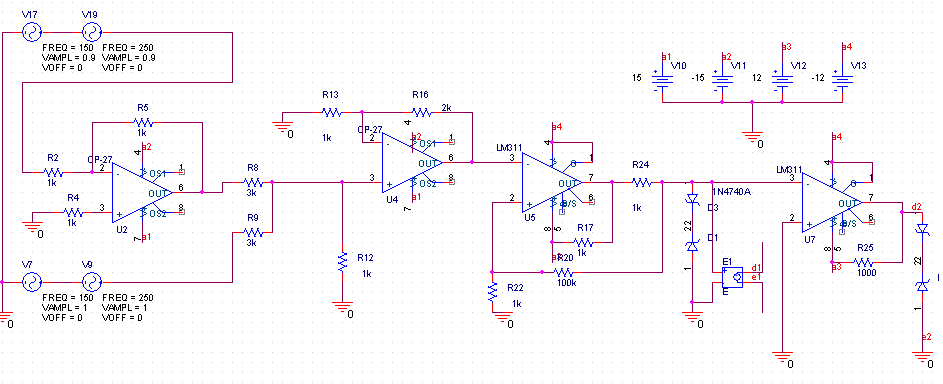
 500) {this.resized=true; this.width=500; this.alt='这是一张缩略图,点击可放大。\n按住CTRL,滚动鼠标滚轮可自由缩放';this.style.cursor='hand'}" onclick="if(!this.resized) {return true;} else {window.open('http://u.dianyuan.com/bbs/u/40/1145583201.gif');}" onmousewheel="return imgzoom(this);">,我想要的是,输入是3.5次谐波,通过滞环比较器,产生控制开关的信号.希望在输出得到的是3,5次谐波电流.
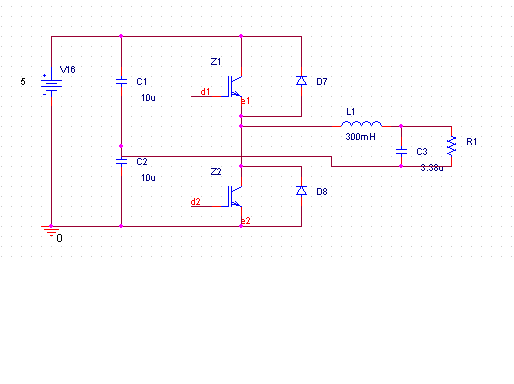
主电路如下:
 500) {this.resized=true; this.width=500; this.alt='这是一张缩略图,点击可放大。\n按住CTRL,滚动鼠标滚轮可自由缩放';this.style.cursor='hand'}" onclick="if(!this.resized) {return true;} else {window.open('http://u.dianyuan.com/bbs/u/40/1145583334.gif');}" onmousewheel="return imgzoom(this);">
采用的是半桥.经过lc滤波,输入的电流很不合人意.
请大家帮我看看,我稍候上传仿真波形

