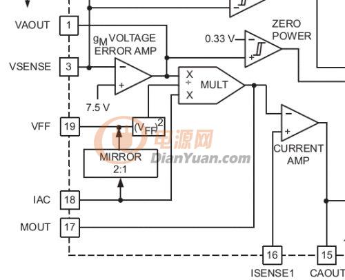
各位:接上回振荡器的建模,再接上乘法器的建模。
MOUT (Pin 17): Theoutput of the multiplier and the input to the current amplifier in the PFCstage are internally connected at this pin. Set the power range of the PFCstage with a resistor tied between the MOUT pin and the non-grounded end of thePFC current sense resistor. Connect impedance between the MOUT pin and the CAOUTpin to compensate the PFC current control loop. The multiplier output is acurrent and the current amplifier input is high impedance. The multiplieroutput current is given by:
VFF (Pin 19): Theoutput current from this pin comes from an internal current mirror that dividesthe IAC input current by 2. The input voltage feedforward signal for themultiplier is then generated across an external single-pole R/C filter connectedbetween VFF and GND. At low line, the VFF voltage should be set to 1.4 V.
此模型为整个的核心,此模型建好后,其它模型直接在Saber现有模型上修改即可。在建模之前有几个Pin的定义必须要了解清楚,否则我们无从下手。
VFF:此Pin用于PFC的电压前馈,用以保证PFC值;我们知道PFC电感的电感是跟踪输入电压kVin和输出电压环VAOUT的乘积的;在高压时Vin=230V,k*Vin*VAOUT较高;低压Vin=90V时k*Vin*VAOUT较低;如果没有前馈,输入电感电流将会与k*Vin*VAOUT成正比,相应的输出功率将与其成正比,这与我们要保证不同Vin条件下Pout保持不变相矛盾,因此我们需要前馈来消除输入电压的影响,保证输出输出功率的恒定;有人认为VAOUT自己会调节,实际中没有前馈光靠VAOUT进行调节是很难保证电路正常工作的。
另外为什么上述公式VFF是平方,其实我们可以通过简单的推导便知,既然IMOUT是电流环的基准,那么IMOUT*Vin必然要是一个常数(功率守恒),而IIAC=Vin/RAC;VFF=kc*IIAC
代入上述公式得到
可以发现结果的确是一个常量,如果不带平方,结果将与Vin成正比,这与功率守恒相矛盾。
\乘法器的建模相对也是比较简单的,我们只要牢牢抓住下面的关系式:
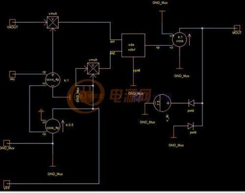
可以发现此公式给出的是无量纲的表达式,里面有电压和电流的混合运算,在saber中我们不好直接将电压与电流相乘;我们知道Saber中有CCVS和VCCS,通过此模板我们就可以方面的将电流或电压转换为电压或电流,并进行相关的代数运算。下图给出乘法器的Saber模型图:
其中7.5V的电压源及二极管用以MOUTPin脚的电压限幅;K=1,此值由Datasheet给出;除法器模型是我基于MAST帮助文档中的vdiv模型修改而来;有关MAST的建模,最近正在学习,目前略懂一二,有兴趣的朋友可以共同讨论一下。
为验证模型的正确性,我们搭建了如下的测试电路进行验证,判断的标准是看IMOUT是否满足上述公式?
下图给出了IMOUT与在Saber Scope中利用公式计算得到的结果比较图,可以发现两者之间有着很好的一致性,说明模型建立正确。
下一步工作准备在乘法器和振荡器的基础上加上电压环和电流环,并进行PFC基本功能的验证。


