• 回复
  • 收藏
  • 点赞
  • 分享
  • 发新帖

LTC3789 四MOS 升降压电路中出现控制信号出错的问题

我采用LTC3789设计了一个输入4~24V,输出5V 6A的电路。但是在测试的时候出现了下面的问题。

我设计时,开关频率设计为600KHz

1、输出纹波过大,并且有一定的尖峰,尖峰频率在150KHz左右,空载时的纹波就已经在100mV了。4A负载时,纹波峰峰值达到了300~400mV。基本上是由于尖峰产生的。

2、仔细检测了尖峰产生的原因。测试条件如下:输入电压12V,输出电压5V,空载。

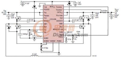
      用示波器检测A、B桥(输入侧)驱动引脚波形正常,属于PWM控制信号。但是C、D桥(输出侧)波形异常。按照datasheet的说明,在降压情况下,应该只有A、B桥工作,C桥应该是常开,D桥应该是常关。相应地就要求C桥的控制信号为高电平,D桥的控制信号为低电平。但是在实现测试时发现C桥为高电平,但是每四个时钟周期就有一个低电平脉冲,D桥为低电平,但是每四个周期就有一个高电平脉冲,导致输出端就有相应地电压尖峰出现,并且转换效率也很低。空载时的输入电流达到了33mA。


全部回复(7)
正序查看
倒序查看
米老鼠
LV.8
2
2012-04-21 15:41
这个IC很贵啊
0
回复
zq2007
LV.11
3
2012-04-22 16:01
@米老鼠
这个IC很贵啊

传一个电路图你参考一下。


0
回复
2012-05-14 18:00

首先,请问楼主的芯片是在哪里买的?假片会出现你所说的现象。

其次,R23,R24电阻偏小,R12和R9的电阻为什么不一样?

在此,差的PCB也会导致这样的现象。

0
回复
ttkx365
LV.5
5
2012-05-14 20:49
信息不够。输出滤波电容是用什么类型的电容?输出没有用大容量的陶瓷电容,输出纹波高就很正常啦,即使用了固态电容,也还嫌不够的。空载电流33mA,在可接受范围内。
0
回复
2012-07-11 14:48
@ttkx365
信息不够。输出滤波电容是用什么类型的电容?输出没有用大容量的陶瓷电容,输出纹波高就很正常啦,即使用了固态电容,也还嫌不够的。空载电流33mA,在可接受范围内。
我们做的控制电流很大有80ma不知道怎么办。。。求大侠帮忙。MOS管型号是IRLR7843.改了频率到200KHZ空载电流下去一点。还有空载时,输出电压变大空载电流也变大
0
回复
ttkx365
LV.5
7
2012-07-11 20:25
@chenweiqihun
我们做的控制电流很大有80ma不知道怎么办。。。求大侠帮忙。MOS管型号是IRLR7843.改了频率到200KHZ空载电流下去一点。还有空载时,输出电压变大空载电流也变大

你反映的信息也不够全面。

曾测试过凌特提供的3789DEMO板。当输入电压为6V输出电压为12V的情况下,静态电流大约在52mA,而当输入电压为9V输出电压为12V的情况下,静态电流大约在33mA,当输入电压为36V输出电压为12V的情况下,静态电流大约在30mA。

DC-DC电路最关键的就是PCB的设计,对于能升能降的这类IC,因为有4个开关管的动作,相对于较简单的BOOST或者BUCK电路,对PCB设计要求就更高了。

所以,要不换其他较简单的IC,要不多尝试更改PCB设计。无论是静态电流的问题还是输出纹波的问题都与PCB布局相关的。

0
回复
kevin.lan
LV.3
8
2012-08-10 15:18

这个IC的设计难点在PCB,可能大多数的人都没去仔细看DATASHEET, 另外因为布线复杂,建议用4层板。仔细看下下面的指导。如果需要技术支持,凌特的FAE愿意为您效劳 Q47401838

Use planes for VIN and VOUT to maintain good voltage
filtering and to keep power losses low.
• Flood all unused areas on all layers with copper. Flooding
with copper will reduce the temperature rise of power
components. Connect the copper areas to any DC
net (VIN or GND). When laying out the printed circuit
board, the following checklist should be used to ensure
proper operation of the LTC3789. These items are also
illustrated in Figure 13.
• Segregate the signal and power grounds. All smallsignal
components should return to the SGND pin at
one point, which is then tied to the PGND pin close to
the inductor current sense resistor RSENSE.
• Place switch B and switch C as close to the controller
as possible, keeping the PGND, BG and SW traces
short.
• Keep the high dV/dT SW1, SW2, BOOST1, BOOST2,
TG1 and TG2 nodes away from sensitive small-signal
nodes.
• The path formed by switch A, switch B, D1 and the CIN
capacitor should have short leads and PC trace lengths.
The path formed by switch C, switch D, D2 and the
COUT capacitor also should have short leads and PC
trace lengths.
• The output capacitor (–) terminals should be connected
as closely as possible to the (–) terminals of the input
capacitor.
• Connect the top driver boost capacitor CA closely to the
BOOST1 and SW1 pins. Connect the top driver boost
capacitor CB closely to the BOOST2 and SW2 pins.
• Connect the input capacitors CIN and output capacitors
COUT closely to the power MOSFETs. These capacitors
carry the MOSFET AC current in the boost and buck
region.
• Connect VFB pin resistive dividers to the (+) terminals of
COUT and signal ground. A small VFB bypass capacitor
may be connected closely to the LTC3789 SGND pin.
The R2 connection should not be along the high current
or noise paths, such as the input capacitors.
• Route SENSE– and SENSE+ leads together with minimum
PC trace spacing. Avoid having sense lines pass
through noisy areas, such as switch nodes. The filter
capacitor between SENSE+ and SENSE– should be as
close as possible to the IC. Ensure accurate current
sensing with Kelvin connections at the SENSE resistor.
One layout example is shown in Figure 14.
• Connect the ITH pin compensation network closely to
the IC, between ITH and the signal ground pins. The
capacitor helps to filter the effects of PCB noise and
output voltage ripple voltage from the compensation
loop.
• Connect the INTVCC bypass capacitor, CVCC, closely
to the IC, between the INTVCC and the power ground
pins. This capacitor carries the MOSFET drivers’ current
peaks. An additional 1μF ceramic capacitor placed immediately
next to the INTVCC and PGND pins can help
improve noise performance substantially.
APPLICATIONS INFORMATION
GND
VOUT

0
回复