
前言:本来是要写个电流波形歪不歪的文章的,最开始是用模型搭的在调试,越调越不爽,于是干脆用代码搞了一个,调试起来还更方便一些,于是就有了下文。对了,电流波形歪头与电压环的100Hz文波有关系,如果用Notching filter抑制住100Hz就可以减弱部分歪头现象,进一步提升THD哟。
环境: Plecs4.1.2
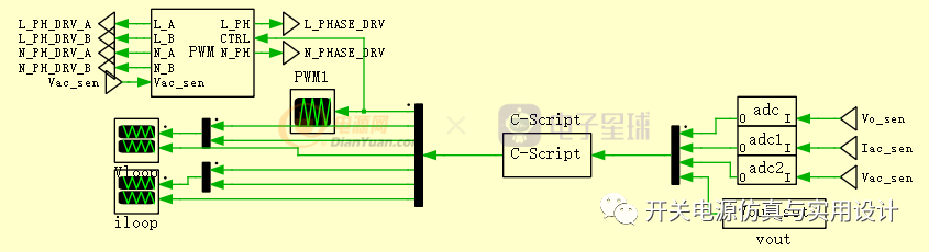
模型框架:

控制和采样:
-
交流电压
-
输出电压
-
电感电流
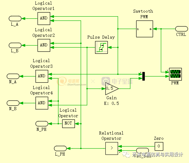
发波:
使用单上升计数的三角波,用电流环的输出直接与其切割产生占空比,为了实现交错,把另一路的脉冲直接延迟了半个开关周期。至于无桥的驱动,就是采样电压相位,分别驱动对应的开关管,原理极其简单,略过不表。
控制方法:
对输出电压使用陷波器抑制100Hz文波,再将其送入电压还。电压还直接乘以AC电压波形,然后送给电流环,电流环输出切三角波产生占空比(搞的比较简单,后续会增加电压前馈进去)。对了,单相PFC电流内环因为要跟随100Hz的电流给定,调试起来比较麻烦。这里我使用了2P2Z来做控制,取得了还不错的效果。
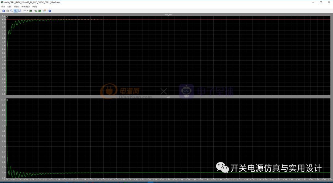
1 满载上电:
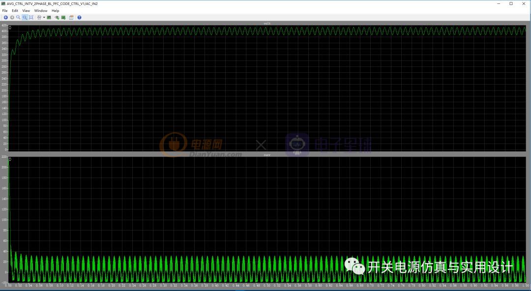
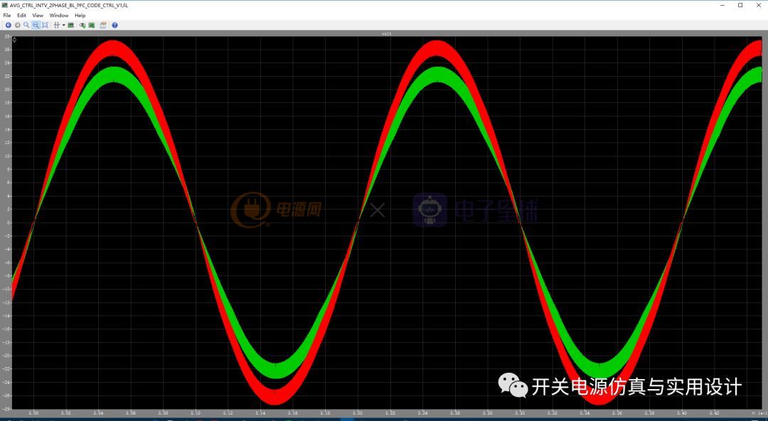
2 输入电流
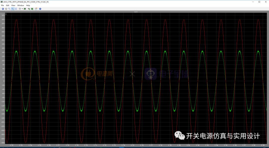
3 两路电感电流:
4 电压环(PI):
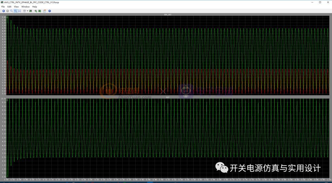
5 电流环(2P2Z):
代码:
//BL PFC CONTROL CODE
//2019/01/05
#include <float.h>
#include <math.h>
//Loop Coefficient define
#define VLOOP_TS 1e-5
#define VLOOP_KP 2.5
#define VLOOP_KI 100
#define VLOOP_KD 0
#define Vloop_UP 10
#define Vloop_LOW 00
#define ILOOP_TS 1e-5
#define ILOOP_KP 2.5
#define ILOOP_KI 50
#define ILOOP_KD 0
#define Iloop_UP 9.95
#define Iloop_LOW 00
//Notching Filter Coefficient
#define Notching_filter_100Hz_GAIN 1
#define Notching_filter_100Hz_B0 0.99984016650191787078938432387076318264
#define Notching_filter_100Hz_B1 -1.999640861026062754746135396999306976795
#define Notching_filter_100Hz_B2 0.99984016650191787078938432387076318264
#define Notching_filter_100Hz_A1 -1.999640861026062754746135396999306976795
#define Notching_filter_100Hz_A2 0.99968033300383574157876864774152636528
//Iloop 2p2z ceofficient
#define iLOOP_B0 -2.5
#define iLOOP_B1 -1.667
#define iLOOP_B2 0.8333
#define iLOOP_A1 -0.33333
#define iLOOP_A2 0.6667
#define iLOOP_OUTMAX 9.985
#define iLOOP_OUTMIN 0
// Control law 2p2z data define
typedef struct CONTROL_LAW_2P2Z_TAG {
double B0;
double B1;
double B2;
double A1;
double A2;
double out_max;
double out_min;
double error_0;
double error_1;
double error_2;
double output_0;
double output_1;
double output_2;
}CONTROL_LAW_2P2Z_DEFINE;
double Control_law_2p2z_func(CONTROL_LAW_2P2Z_DEFINE *ctrl_law, double target_reality_value, double control_give_value)
{
// calculate the error
ctrl_law->error_0 = control_give_value - target_reality_value;
//
// y[n] = B0 * e[n] + B1 * e[n-1] + B2 * e[n-2] - A1 * y[n-1] - A2 * y[n-2]
// Discrete difference equation
//
ctrl_law->output_0 = (ctrl_law->B0 * ctrl_law->error_0 + ctrl_law->B1 * ctrl_law->error_1 \
+ ctrl_law->B2 * ctrl_law->error_2 - ctrl_law->A1 * ctrl_law->output_1 \
- ctrl_law->A2 * ctrl_law->output_2);
//
// output integral limit
//
if(ctrl_law->output_0 > ctrl_law->out_max) { ctrl_law->output_0 = ctrl_law->out_max; }
if(ctrl_law->output_0 < ctrl_law->out_min) { ctrl_law->output_0 = ctrl_law->out_min; }
//
// Update last cycle value
//
ctrl_law->output_1 = ctrl_law->output_0;
ctrl_law->output_2 = ctrl_law->output_1;
ctrl_law->error_1 = ctrl_law->error_0;
ctrl_law->error_2 = ctrl_law->error_1;
double calculate_result_2p2z = (ctrl_law->out_max - ctrl_law->output_0);
if(calculate_result_2p2z > ctrl_law->out_max) { calculate_result_2p2z = ctrl_law->out_max; }
if(calculate_result_2p2z < ctrl_law->out_min) { calculate_result_2p2z = ctrl_law->out_min; }
//
// Return calculate result
//
return(calculate_result_2p2z);
}
//
// data struct define
//
typedef struct PI_CTRL_DATA_TAG {
double ts;
double kp;
double ki;
double kd;
double up_limt;
double low_limt;
double a0;
double a1;
double a2;
double out;
double out_1;
double error;
double error_1;
double error_2;
} PI_CTRL_DATA_DEF;
typedef struct Notching_filter_data_Tag{
double coeff_GAIN;
double coeff_B0;
double coeff_B1;
double coeff_B2;
double coeff_A1;
double coeff_A2;
double filter_out;
double filter_W0;
double filter_W1;
double filter_W2;
} Notching_filter_DATA_DEF;
//
// Function Des
//
double pi_func(PI_CTRL_DATA_DEF *pi, double give, double sen)
{
pi->error = give - sen;
pi->a0 = pi->kp + pi->ki * pi->ts + pi->kd / pi->ts;
pi->a1 = pi->kp + 2 * pi->kd / pi->ts;
pi->a2 = pi->kd / pi->ts;
pi->out = pi->out_1 + pi->a0 * pi->error - pi->a1 * pi->error_1 + pi->a2 * pi->error_2;
// Limt
if(pi->out > pi->up_limt) pi->out = pi->up_limt;
if(pi->out < pi->low_limt) pi->out = pi->low_limt;
pi->out_1 = pi->out;
pi->error_1 = pi->error;
pi->error_2 = pi->error_1;
return(pi->out);
}
double Notching_filter_func(Notching_filter_DATA_DEF *filter_date, double target)
{
//
// w0 = x(0) - A1 * W1 - A2 * W2
//
filter_date->filter_W0 = (target) - filter_date->coeff_A1 * filter_date->filter_W1 \
- filter_date->coeff_A2 * filter_date->filter_W2;
//
// Y(0) = Gain * (B0 * W0 + B1 * W1 + B2 * W2)
//
filter_date->filter_out = filter_date->coeff_GAIN * ( filter_date->coeff_B0 * filter_date->filter_W0 \
+ filter_date->coeff_B1 * filter_date->filter_W1 \
+ filter_date->coeff_B2 * filter_date->filter_W2 );
//
// Update last data
//
filter_date->filter_W2 = filter_date->filter_W1;
filter_date->filter_W1 = filter_date->filter_W0;
//
// Return Value
//
return(filter_date->filter_out);
}
//
//INIT PI COEFF
//
PI_CTRL_DATA_DEF vloop_pi = {
VLOOP_TS,
VLOOP_KP,
VLOOP_KI,
VLOOP_KD,
Vloop_UP,
Vloop_LOW,
0, 0, 0,
0, 0,
0, 0, 0
};
PI_CTRL_DATA_DEF iloop_pi = {
ILOOP_TS,
ILOOP_KP,
ILOOP_KI,
ILOOP_KD,
Iloop_UP,
Iloop_LOW,
0, 0, 0,
0, 0,
0, 0, 0
};
Notching_filter_DATA_DEF notching_data = {
Notching_filter_100Hz_GAIN,
Notching_filter_100Hz_B0,
Notching_filter_100Hz_B1,
Notching_filter_100Hz_B2,
Notching_filter_100Hz_A1,
Notching_filter_100Hz_A2,
0, 0, 0, 0
};
CONTROL_LAW_2P2Z_DEFINE iloop_2p2z_data = {
iLOOP_B0,
iLOOP_B1,
iLOOP_B2,
iLOOP_A1,
iLOOP_A2,
iLOOP_OUTMAX,
iLOOP_OUTMIN,
0, 0, 0, 0, 0, 0
};//OUTPUT FUNC#include <math.h>
//output_func
//define I/O
double vbussen = InputSignal(0, 0);
double Isen = InputSignal(0, 1);
double Vacsen = InputSignal(0, 2);
double vset = InputSignal(0, 3);
//Handle vbus 100hz
double vbus = Notching_filter_func(¬ching_data, vbussen);
//Call Voltage loop
double vloop_out = pi_func(&vloop_pi, vset, vbus);
//mult func
double iloop_set = (vloop_out * fabs(Vacsen));
//Call Current loop
double iloop_out = Control_law_2p2z_func(&iloop_2p2z_data, fabs(Isen), iloop_set);
//output control value
OutputSignal(0, 0) = iloop_out;
//debug
OutputSignal(0, 1) = vbus;
OutputSignal(0, 2) = vset;
OutputSignal(0, 3) = vloop_out;
OutputSignal(0, 4) = fabs(Isen);
OutputSignal(0, 5) = iloop_set;
OutputSignal(0, 6) = iloop_out;以上,谢谢观看~~