 500) {this.resized=true; this.width=500; this.alt='这是一张缩略图,点击可放大。\n按住CTRL,滚动鼠标滚轮可自由缩放';this.style.cursor='hand'}" onclick="if(!this.resized) {return true;} else {window.open('http://u.dianyuan.com/bbs/u/28/1113485864.gif');}" onmousewheel="return imgzoom(this);">
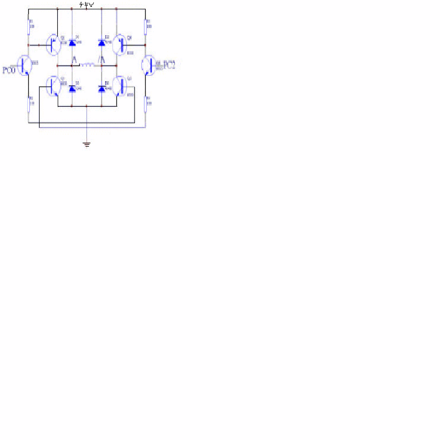
各位大仙,帮我分析一个简单模拟电路图
该图是用单片机控制步进电机的驱动电路图,其中PC0,PC2是单片机输出的信号,PC0=5V,PC2=0V,或PC0=0V,PC2=5V(电路中的输入),A和/A是步进电机一相的两端,A,/A间40欧姆电阻,要求A,/A间有5V电压,且轮流通电,请问该怎么选择电路图上元件的型号和大小(如三极管选9012,9013等)(图上文字看不清,请帮忙分析下)
 500) {this.resized=true; this.width=500; this.alt='这是一张缩略图,点击可放大。\n按住CTRL,滚动鼠标滚轮可自由缩放';this.style.cursor='hand'}" onclick="if(!this.resized) {return true;} else {window.open('http://u.dianyuan.com/bbs/u/28/1113485864.gif');}" onmousewheel="return imgzoom(this);">
 500) {this.resized=true; this.width=500; this.alt='这是一张缩略图,点击可放大。\n按住CTRL,滚动鼠标滚轮可自由缩放';this.style.cursor='hand'}" onclick="if(!this.resized) {return true;} else {window.open('http://u.dianyuan.com/bbs/u/28/1113485864.gif');}" onmousewheel="return imgzoom(this);">
 500) {this.resized=true; this.width=500; this.alt='这是一张缩略图,点击可放大。\n按住CTRL,滚动鼠标滚轮可自由缩放';this.style.cursor='hand'}" onclick="if(!this.resized) {return true;} else {window.open('http://u.dianyuan.com/bbs/u/28/1113494928.gif');}" onmousewheel="return imgzoom(this);">