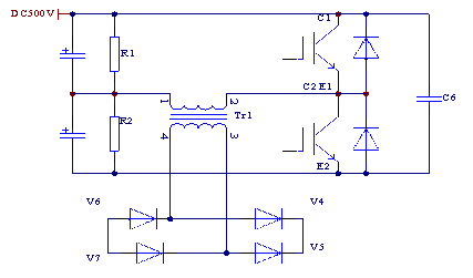
 500) {this.resized=true; this.width=500; this.alt='这是一张缩略图,点击可放大。\n按住CTRL,滚动鼠标滚轮可自由缩放';this.style.cursor='hand'}" onclick="if(!this.resized) {return true;} else {window.open('http://u.dianyuan.com/bbs/u/35/1132030450.gif');}" onmousewheel="return imgzoom(this);">
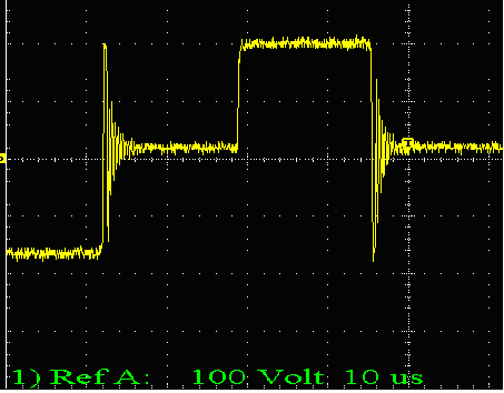
在输入电压为DC500V,我用示波器所测的变压器的原次边波形,其中原边波形如图:
 500) {this.resized=true; this.width=500; this.alt='这是一张缩略图,点击可放大。\n按住CTRL,滚动鼠标滚轮可自由缩放';this.style.cursor='hand'}" onclick="if(!this.resized) {return true;} else {window.open('http://u.dianyuan.com/bbs/u/35/1132030614.gif');}" onmousewheel="return imgzoom(this);">
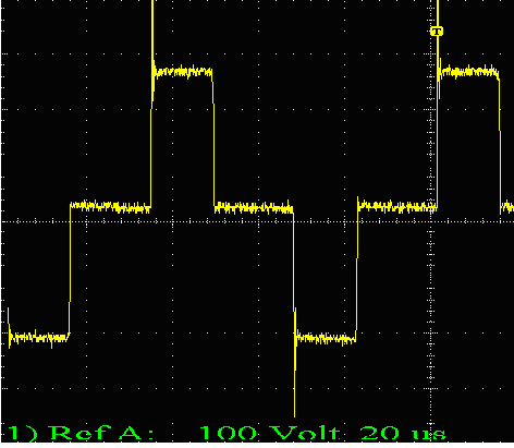
次边波形如图:
 500) {this.resized=true; this.width=500; this.alt='这是一张缩略图,点击可放大。\n按住CTRL,滚动鼠标滚轮可自由缩放';this.style.cursor='hand'}" onclick="if(!this.resized) {return true;} else {window.open('http://u.dianyuan.com/bbs/u/35/1132030649.gif');}" onmousewheel="return imgzoom(this);">.其中次边已经加入RC吸收电路(R=32,C=4.4nF).
请高手帮忙分析下次边的尖峰是怎么产生的,加怎么样的吸收电路比较理想?

