在下设计电感时,选用了一副EE65的铁氧体磁芯,Bm取0.15T,ur取2000.要求是感值113mH,且加1.4V(rms)/50Hz正弦电压不饱和.根据感值要求算得N为111,根据伏秒算得N至少为80匝.我取了112匝.测量时,感值基本达到要求,可是从电流波形上看,到1.4V时,电流已经不是很标准的正弦波了.我不知道是设计的方法有误,还是磁芯参数选择的问题.在此望各位高手不吝赐教!先谢了!
2575981240886391.rar
电感饱和
全部回复(15)
正序查看
倒序查看
现在还没有回复呢,说说你的想法
上传的附件好像有问题.我把波形直接贴出来:
CH3为电压波形,CH4为电流波形;
1. 0.6V输入:
 500) {this.resized=true; this.width=500; this.alt='这是一张缩略图,点击可放大。\n按住CTRL,滚动鼠标滚轮可自由缩放';this.style.cursor='hand'}" onclick="if(!this.resized) {return true;} else {window.open('http://u.dianyuan.com/bbs/u/76/2575981240927141.jpg');}" onmousewheel="return imgzoom(this);">
2. 1.4V输入:
 500) {this.resized=true; this.width=500; this.alt='这是一张缩略图,点击可放大。\n按住CTRL,滚动鼠标滚轮可自由缩放';this.style.cursor='hand'}" onclick="if(!this.resized) {return true;} else {window.open('http://u.dianyuan.com/bbs/u/76/2575981240927187.jpg');}" onmousewheel="return imgzoom(this);">
3. 2.0V输入:
 500) {this.resized=true; this.width=500; this.alt='这是一张缩略图,点击可放大。\n按住CTRL,滚动鼠标滚轮可自由缩放';this.style.cursor='hand'}" onclick="if(!this.resized) {return true;} else {window.open('http://u.dianyuan.com/bbs/u/76/2575981240927207.jpg');}" onmousewheel="return imgzoom(this);">
4. 4.0V输入:
 500) {this.resized=true; this.width=500; this.alt='这是一张缩略图,点击可放大。\n按住CTRL,滚动鼠标滚轮可自由缩放';this.style.cursor='hand'}" onclick="if(!this.resized) {return true;} else {window.open('http://u.dianyuan.com/bbs/u/76/2575981240927233.jpg');}" onmousewheel="return imgzoom(this);">
5. 7.0V输入:
 500) {this.resized=true; this.width=500; this.alt='这是一张缩略图,点击可放大。\n按住CTRL,滚动鼠标滚轮可自由缩放';this.style.cursor='hand'}" onclick="if(!this.resized) {return true;} else {window.open('http://u.dianyuan.com/bbs/u/76/2575981240927262.jpg');}" onmousewheel="return imgzoom(this);">
CH3为电压波形,CH4为电流波形;
1. 0.6V输入:
 500) {this.resized=true; this.width=500; this.alt='这是一张缩略图,点击可放大。\n按住CTRL,滚动鼠标滚轮可自由缩放';this.style.cursor='hand'}" onclick="if(!this.resized) {return true;} else {window.open('http://u.dianyuan.com/bbs/u/76/2575981240927141.jpg');}" onmousewheel="return imgzoom(this);">
2. 1.4V输入:
 500) {this.resized=true; this.width=500; this.alt='这是一张缩略图,点击可放大。\n按住CTRL,滚动鼠标滚轮可自由缩放';this.style.cursor='hand'}" onclick="if(!this.resized) {return true;} else {window.open('http://u.dianyuan.com/bbs/u/76/2575981240927187.jpg');}" onmousewheel="return imgzoom(this);">
3. 2.0V输入:
 500) {this.resized=true; this.width=500; this.alt='这是一张缩略图,点击可放大。\n按住CTRL,滚动鼠标滚轮可自由缩放';this.style.cursor='hand'}" onclick="if(!this.resized) {return true;} else {window.open('http://u.dianyuan.com/bbs/u/76/2575981240927207.jpg');}" onmousewheel="return imgzoom(this);">
4. 4.0V输入:
 500) {this.resized=true; this.width=500; this.alt='这是一张缩略图,点击可放大。\n按住CTRL,滚动鼠标滚轮可自由缩放';this.style.cursor='hand'}" onclick="if(!this.resized) {return true;} else {window.open('http://u.dianyuan.com/bbs/u/76/2575981240927233.jpg');}" onmousewheel="return imgzoom(this);">
5. 7.0V输入:
 500) {this.resized=true; this.width=500; this.alt='这是一张缩略图,点击可放大。\n按住CTRL,滚动鼠标滚轮可自由缩放';this.style.cursor='hand'}" onclick="if(!this.resized) {return true;} else {window.open('http://u.dianyuan.com/bbs/u/76/2575981240927262.jpg');}" onmousewheel="return imgzoom(this);">
 0
回复
提示
@ruford
上传的附件好像有问题.我把波形直接贴出来:CH3为电压波形,CH4为电流波形;1.0.6V输入:[图片]500){this.resized=true;this.width=500;this.alt='这是一张缩略图,点击可放大。\n按住CTRL,滚动鼠标滚轮可自由缩放';this.style.cursor='hand'}"onclick="if(!this.resized){returntrue;}else{window.open('http://u.dianyuan.com/bbs/u/76/2575981240927141.jpg');}"onmousewheel="returnimgzoom(this);">2.1.4V输入:[图片]500){this.resized=true;this.width=500;this.alt='这是一张缩略图,点击可放大。\n按住CTRL,滚动鼠标滚轮可自由缩放';this.style.cursor='hand'}"onclick="if(!this.resized){returntrue;}else{window.open('http://u.dianyuan.com/bbs/u/76/2575981240927187.jpg');}"onmousewheel="returnimgzoom(this);">3.2.0V输入:[图片]500){this.resized=true;this.width=500;this.alt='这是一张缩略图,点击可放大。\n按住CTRL,滚动鼠标滚轮可自由缩放';this.style.cursor='hand'}"onclick="if(!this.resized){returntrue;}else{window.open('http://u.dianyuan.com/bbs/u/76/2575981240927207.jpg');}"onmousewheel="returnimgzoom(this);">4.4.0V输入:[图片]500){this.resized=true;this.width=500;this.alt='这是一张缩略图,点击可放大。\n按住CTRL,滚动鼠标滚轮可自由缩放';this.style.cursor='hand'}"onclick="if(!this.resized){returntrue;}else{window.open('http://u.dianyuan.com/bbs/u/76/2575981240927233.jpg');}"onmousewheel="returnimgzoom(this);">5.7.0V输入:[图片]500){this.resized=true;this.width=500;this.alt='这是一张缩略图,点击可放大。\n按住CTRL,滚动鼠标滚轮可自由缩放';this.style.cursor='hand'}"onclick="if(!this.resized){returntrue;}else{window.open('http://u.dianyuan.com/bbs/u/76/2575981240927262.jpg');}"onmousewheel="returnimgzoom(this);">
顶一个
0
回复
提示
@sixbrother
关键是它不适用于50HZ!就好比用矽钢加几百khz的频率一样不适合!
感谢你的指教!
但是不知道1.2kHz的频率是否合适?
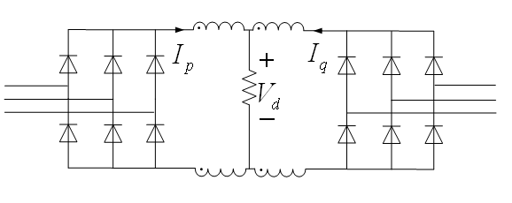
这个感是用来做为115V/400Hz输入的两个三相整流桥并联输出(即12脉冲整流)时的平衡电抗器的,感上的电压频率为1.2kHz.
80匝是根据115V输入时电感上的伏秒计算出不饱和的最少匝数的结果,Bm取的是1500Gs.实验中取的是112匝,可还是发现当输入电压加到50多伏时,电流波形上就开始出现尖峰.下图是115V输入时感上的电流波形:
1. 电路:
 500) {this.resized=true; this.width=500; this.alt='这是一张缩略图,点击可放大。\n按住CTRL,滚动鼠标滚轮可自由缩放';this.style.cursor='hand'}" onclick="if(!this.resized) {return true;} else {window.open('http://u.dianyuan.com/bbs/u/76/2575981240983895.gif');}" onmousewheel="return imgzoom(this);">
2. 115V输入时Vd、Ip:
 500) {this.resized=true; this.width=500; this.alt='这是一张缩略图,点击可放大。\n按住CTRL,滚动鼠标滚轮可自由缩放';this.style.cursor='hand'}" onclick="if(!this.resized) {return true;} else {window.open('http://u.dianyuan.com/bbs/u/76/2575981240984042.jpg');}" onmousewheel="return imgzoom(this);">
3. 115V输入时Vd、Iq:
 500) {this.resized=true; this.width=500; this.alt='这是一张缩略图,点击可放大。\n按住CTRL,滚动鼠标滚轮可自由缩放';this.style.cursor='hand'}" onclick="if(!this.resized) {return true;} else {window.open('http://u.dianyuan.com/bbs/u/76/2575981240984095.jpg');}" onmousewheel="return imgzoom(this);">
但是不知道1.2kHz的频率是否合适?
这个感是用来做为115V/400Hz输入的两个三相整流桥并联输出(即12脉冲整流)时的平衡电抗器的,感上的电压频率为1.2kHz.
80匝是根据115V输入时电感上的伏秒计算出不饱和的最少匝数的结果,Bm取的是1500Gs.实验中取的是112匝,可还是发现当输入电压加到50多伏时,电流波形上就开始出现尖峰.下图是115V输入时感上的电流波形:
1. 电路:
 500) {this.resized=true; this.width=500; this.alt='这是一张缩略图,点击可放大。\n按住CTRL,滚动鼠标滚轮可自由缩放';this.style.cursor='hand'}" onclick="if(!this.resized) {return true;} else {window.open('http://u.dianyuan.com/bbs/u/76/2575981240983895.gif');}" onmousewheel="return imgzoom(this);">
2. 115V输入时Vd、Ip:
 500) {this.resized=true; this.width=500; this.alt='这是一张缩略图,点击可放大。\n按住CTRL,滚动鼠标滚轮可自由缩放';this.style.cursor='hand'}" onclick="if(!this.resized) {return true;} else {window.open('http://u.dianyuan.com/bbs/u/76/2575981240984042.jpg');}" onmousewheel="return imgzoom(this);">
3. 115V输入时Vd、Iq:
 500) {this.resized=true; this.width=500; this.alt='这是一张缩略图,点击可放大。\n按住CTRL,滚动鼠标滚轮可自由缩放';this.style.cursor='hand'}" onclick="if(!this.resized) {return true;} else {window.open('http://u.dianyuan.com/bbs/u/76/2575981240984095.jpg');}" onmousewheel="return imgzoom(this);">
 0
回复
提示
@ruford
感谢你的指教!但是不知道1.2kHz的频率是否合适?这个感是用来做为115V/400Hz输入的两个三相整流桥并联输出(即12脉冲整流)时的平衡电抗器的,感上的电压频率为1.2kHz.80匝是根据115V输入时电感上的伏秒计算出不饱和的最少匝数的结果,Bm取的是1500Gs.实验中取的是112匝,可还是发现当输入电压加到50多伏时,电流波形上就开始出现尖峰.下图是115V输入时感上的电流波形:1.电路:[图片]500){this.resized=true;this.width=500;this.alt='这是一张缩略图,点击可放大。\n按住CTRL,滚动鼠标滚轮可自由缩放';this.style.cursor='hand'}"onclick="if(!this.resized){returntrue;}else{window.open('http://u.dianyuan.com/bbs/u/76/2575981240983895.gif');}"onmousewheel="returnimgzoom(this);">2.115V输入时Vd、Ip:[图片]500){this.resized=true;this.width=500;this.alt='这是一张缩略图,点击可放大。\n按住CTRL,滚动鼠标滚轮可自由缩放';this.style.cursor='hand'}"onclick="if(!this.resized){returntrue;}else{window.open('http://u.dianyuan.com/bbs/u/76/2575981240984042.jpg');}"onmousewheel="returnimgzoom(this);">3.115V输入时Vd、Iq:[图片]500){this.resized=true;this.width=500;this.alt='这是一张缩略图,点击可放大。\n按住CTRL,滚动鼠标滚轮可自由缩放';this.style.cursor='hand'}"onclick="if(!this.resized){returntrue;}else{window.open('http://u.dianyuan.com/bbs/u/76/2575981240984095.jpg');}"onmousewheel="returnimgzoom(this);">
选材错误,不该用EE65的铁氧体!
0
回复
提示
@arhui88
用z110.2~0.25mm厚的矽钢片.
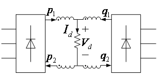
谢谢你的指点.我也在文献中看到选用硅钢片的介绍.不过由于手头没有,就暂时用铁氧体替代了.最近换了个三相交流源,拍到的实验波形和之前的有所不同.
图1. 电路图:
 500) {this.resized=true; this.width=500; this.alt='这是一张缩略图,点击可放大。\n按住CTRL,滚动鼠标滚轮可自由缩放';this.style.cursor='hand'}" onclick="if(!this.resized) {return true;} else {window.open('http://u.dianyuan.com/bbs/u/77/2575981241701159.gif');}" onmousewheel="return imgzoom(this);">
下面是整流桥的四个输出端的电流波形:
图2. 从上到下依次为输出电压Vd、Ip1、上平衡电抗器中点电位(是相对于三相输入中点,下同,前端移相变压器采用的是自耦式):
 500) {this.resized=true; this.width=500; this.alt='这是一张缩略图,点击可放大。\n按住CTRL,滚动鼠标滚轮可自由缩放';this.style.cursor='hand'}" onclick="if(!this.resized) {return true;} else {window.open('http://u.dianyuan.com/bbs/u/77/2575981241701348.jpg');}" onmousewheel="return imgzoom(this);">
图3. 从上到下依次为输出电压Vd、Iq1、上平衡电抗器中点电位:
 500) {this.resized=true; this.width=500; this.alt='这是一张缩略图,点击可放大。\n按住CTRL,滚动鼠标滚轮可自由缩放';this.style.cursor='hand'}" onclick="if(!this.resized) {return true;} else {window.open('http://u.dianyuan.com/bbs/u/77/2575981241701362.jpg');}" onmousewheel="return imgzoom(this);">
图4. 从上到下依次为输出电压Vd、Ip2、下平衡电抗器中点电位:
 500) {this.resized=true; this.width=500; this.alt='这是一张缩略图,点击可放大。\n按住CTRL,滚动鼠标滚轮可自由缩放';this.style.cursor='hand'}" onclick="if(!this.resized) {return true;} else {window.open('http://u.dianyuan.com/bbs/u/77/2575981241701381.jpg');}" onmousewheel="return imgzoom(this);">
图5. 从上到下依次为输出电压Vd、Iq2、下平衡电抗器中点电位:
 500) {this.resized=true; this.width=500; this.alt='这是一张缩略图,点击可放大。\n按住CTRL,滚动鼠标滚轮可自由缩放';this.style.cursor='hand'}" onclick="if(!this.resized) {return true;} else {window.open('http://u.dianyuan.com/bbs/u/77/2575981241701467.jpg');}" onmousewheel="return imgzoom(this);">
图6. 两个平衡电抗器上的电压波形:
 500) {this.resized=true; this.width=500; this.alt='这是一张缩略图,点击可放大。\n按住CTRL,滚动鼠标滚轮可自由缩放';this.style.cursor='hand'}" onclick="if(!this.resized) {return true;} else {window.open('http://u.dianyuan.com/bbs/u/77/2575981241701531.jpg');}" onmousewheel="return imgzoom(this);">
从上面的波形可以看出,两整流的正输出端电流Ip1、Iq1还算正常,负输出端电流Ip2、Iq2中尖峰较大,且四个电流波形中不正常的位置貌似与平衡电抗器的中点电位中的较小的脉波对应.
而且我对两个平衡电抗器进行了对换,可还是在两整流桥的负输出端的电流波形上存在较大的尖峰.
望各位高手能够指点一下小弟,帮忙解释一下电流尖峰出现的原因.
图1. 电路图:
 500) {this.resized=true; this.width=500; this.alt='这是一张缩略图,点击可放大。\n按住CTRL,滚动鼠标滚轮可自由缩放';this.style.cursor='hand'}" onclick="if(!this.resized) {return true;} else {window.open('http://u.dianyuan.com/bbs/u/77/2575981241701159.gif');}" onmousewheel="return imgzoom(this);">
下面是整流桥的四个输出端的电流波形:
图2. 从上到下依次为输出电压Vd、Ip1、上平衡电抗器中点电位(是相对于三相输入中点,下同,前端移相变压器采用的是自耦式):
 500) {this.resized=true; this.width=500; this.alt='这是一张缩略图,点击可放大。\n按住CTRL,滚动鼠标滚轮可自由缩放';this.style.cursor='hand'}" onclick="if(!this.resized) {return true;} else {window.open('http://u.dianyuan.com/bbs/u/77/2575981241701348.jpg');}" onmousewheel="return imgzoom(this);">
图3. 从上到下依次为输出电压Vd、Iq1、上平衡电抗器中点电位:
 500) {this.resized=true; this.width=500; this.alt='这是一张缩略图,点击可放大。\n按住CTRL,滚动鼠标滚轮可自由缩放';this.style.cursor='hand'}" onclick="if(!this.resized) {return true;} else {window.open('http://u.dianyuan.com/bbs/u/77/2575981241701362.jpg');}" onmousewheel="return imgzoom(this);">
图4. 从上到下依次为输出电压Vd、Ip2、下平衡电抗器中点电位:
 500) {this.resized=true; this.width=500; this.alt='这是一张缩略图,点击可放大。\n按住CTRL,滚动鼠标滚轮可自由缩放';this.style.cursor='hand'}" onclick="if(!this.resized) {return true;} else {window.open('http://u.dianyuan.com/bbs/u/77/2575981241701381.jpg');}" onmousewheel="return imgzoom(this);">
图5. 从上到下依次为输出电压Vd、Iq2、下平衡电抗器中点电位:
 500) {this.resized=true; this.width=500; this.alt='这是一张缩略图,点击可放大。\n按住CTRL,滚动鼠标滚轮可自由缩放';this.style.cursor='hand'}" onclick="if(!this.resized) {return true;} else {window.open('http://u.dianyuan.com/bbs/u/77/2575981241701467.jpg');}" onmousewheel="return imgzoom(this);">
图6. 两个平衡电抗器上的电压波形:
 500) {this.resized=true; this.width=500; this.alt='这是一张缩略图,点击可放大。\n按住CTRL,滚动鼠标滚轮可自由缩放';this.style.cursor='hand'}" onclick="if(!this.resized) {return true;} else {window.open('http://u.dianyuan.com/bbs/u/77/2575981241701531.jpg');}" onmousewheel="return imgzoom(this);">
从上面的波形可以看出,两整流的正输出端电流Ip1、Iq1还算正常,负输出端电流Ip2、Iq2中尖峰较大,且四个电流波形中不正常的位置貌似与平衡电抗器的中点电位中的较小的脉波对应.
而且我对两个平衡电抗器进行了对换,可还是在两整流桥的负输出端的电流波形上存在较大的尖峰.
望各位高手能够指点一下小弟,帮忙解释一下电流尖峰出现的原因.
0
回复
提示
@ruford
谢谢你的指点.我也在文献中看到选用硅钢片的介绍.不过由于手头没有,就暂时用铁氧体替代了.最近换了个三相交流源,拍到的实验波形和之前的有所不同.图1.电路图:[图片]500){this.resized=true;this.width=500;this.alt='这是一张缩略图,点击可放大。\n按住CTRL,滚动鼠标滚轮可自由缩放';this.style.cursor='hand'}"onclick="if(!this.resized){returntrue;}else{window.open('http://u.dianyuan.com/bbs/u/77/2575981241701159.gif');}"onmousewheel="returnimgzoom(this);">下面是整流桥的四个输出端的电流波形:图2.从上到下依次为输出电压Vd、Ip1、上平衡电抗器中点电位(是相对于三相输入中点,下同,前端移相变压器采用的是自耦式):[图片]500){this.resized=true;this.width=500;this.alt='这是一张缩略图,点击可放大。\n按住CTRL,滚动鼠标滚轮可自由缩放';this.style.cursor='hand'}"onclick="if(!this.resized){returntrue;}else{window.open('http://u.dianyuan.com/bbs/u/77/2575981241701348.jpg');}"onmousewheel="returnimgzoom(this);">图3.从上到下依次为输出电压Vd、Iq1、上平衡电抗器中点电位:[图片]500){this.resized=true;this.width=500;this.alt='这是一张缩略图,点击可放大。\n按住CTRL,滚动鼠标滚轮可自由缩放';this.style.cursor='hand'}"onclick="if(!this.resized){returntrue;}else{window.open('http://u.dianyuan.com/bbs/u/77/2575981241701362.jpg');}"onmousewheel="returnimgzoom(this);">图4.从上到下依次为输出电压Vd、Ip2、下平衡电抗器中点电位:[图片]500){this.resized=true;this.width=500;this.alt='这是一张缩略图,点击可放大。\n按住CTRL,滚动鼠标滚轮可自由缩放';this.style.cursor='hand'}"onclick="if(!this.resized){returntrue;}else{window.open('http://u.dianyuan.com/bbs/u/77/2575981241701381.jpg');}"onmousewheel="returnimgzoom(this);">图5.从上到下依次为输出电压Vd、Iq2、下平衡电抗器中点电位:[图片]500){this.resized=true;this.width=500;this.alt='这是一张缩略图,点击可放大。\n按住CTRL,滚动鼠标滚轮可自由缩放';this.style.cursor='hand'}"onclick="if(!this.resized){returntrue;}else{window.open('http://u.dianyuan.com/bbs/u/77/2575981241701467.jpg');}"onmousewheel="returnimgzoom(this);">图6.两个平衡电抗器上的电压波形:[图片]500){this.resized=true;this.width=500;this.alt='这是一张缩略图,点击可放大。\n按住CTRL,滚动鼠标滚轮可自由缩放';this.style.cursor='hand'}"onclick="if(!this.resized){returntrue;}else{window.open('http://u.dianyuan.com/bbs/u/77/2575981241701531.jpg');}"onmousewheel="returnimgzoom(this);">从上面的波形可以看出,两整流的正输出端电流Ip1、Iq1还算正常,负输出端电流Ip2、Iq2中尖峰较大,且四个电流波形中不正常的位置貌似与平衡电抗器的中点电位中的较小的脉波对应.而且我对两个平衡电抗器进行了对换,可还是在两整流桥的负输出端的电流波形上存在较大的尖峰.望各位高手能够指点一下小弟,帮忙解释一下电流尖峰出现的原因.
up up
请说重点...
请说重点...
0
回复
提示
@ruford
谢谢你的指点.我也在文献中看到选用硅钢片的介绍.不过由于手头没有,就暂时用铁氧体替代了.最近换了个三相交流源,拍到的实验波形和之前的有所不同.图1.电路图:[图片]500){this.resized=true;this.width=500;this.alt='这是一张缩略图,点击可放大。\n按住CTRL,滚动鼠标滚轮可自由缩放';this.style.cursor='hand'}"onclick="if(!this.resized){returntrue;}else{window.open('http://u.dianyuan.com/bbs/u/77/2575981241701159.gif');}"onmousewheel="returnimgzoom(this);">下面是整流桥的四个输出端的电流波形:图2.从上到下依次为输出电压Vd、Ip1、上平衡电抗器中点电位(是相对于三相输入中点,下同,前端移相变压器采用的是自耦式):[图片]500){this.resized=true;this.width=500;this.alt='这是一张缩略图,点击可放大。\n按住CTRL,滚动鼠标滚轮可自由缩放';this.style.cursor='hand'}"onclick="if(!this.resized){returntrue;}else{window.open('http://u.dianyuan.com/bbs/u/77/2575981241701348.jpg');}"onmousewheel="returnimgzoom(this);">图3.从上到下依次为输出电压Vd、Iq1、上平衡电抗器中点电位:[图片]500){this.resized=true;this.width=500;this.alt='这是一张缩略图,点击可放大。\n按住CTRL,滚动鼠标滚轮可自由缩放';this.style.cursor='hand'}"onclick="if(!this.resized){returntrue;}else{window.open('http://u.dianyuan.com/bbs/u/77/2575981241701362.jpg');}"onmousewheel="returnimgzoom(this);">图4.从上到下依次为输出电压Vd、Ip2、下平衡电抗器中点电位:[图片]500){this.resized=true;this.width=500;this.alt='这是一张缩略图,点击可放大。\n按住CTRL,滚动鼠标滚轮可自由缩放';this.style.cursor='hand'}"onclick="if(!this.resized){returntrue;}else{window.open('http://u.dianyuan.com/bbs/u/77/2575981241701381.jpg');}"onmousewheel="returnimgzoom(this);">图5.从上到下依次为输出电压Vd、Iq2、下平衡电抗器中点电位:[图片]500){this.resized=true;this.width=500;this.alt='这是一张缩略图,点击可放大。\n按住CTRL,滚动鼠标滚轮可自由缩放';this.style.cursor='hand'}"onclick="if(!this.resized){returntrue;}else{window.open('http://u.dianyuan.com/bbs/u/77/2575981241701467.jpg');}"onmousewheel="returnimgzoom(this);">图6.两个平衡电抗器上的电压波形:[图片]500){this.resized=true;this.width=500;this.alt='这是一张缩略图,点击可放大。\n按住CTRL,滚动鼠标滚轮可自由缩放';this.style.cursor='hand'}"onclick="if(!this.resized){returntrue;}else{window.open('http://u.dianyuan.com/bbs/u/77/2575981241701531.jpg');}"onmousewheel="returnimgzoom(this);">从上面的波形可以看出,两整流的正输出端电流Ip1、Iq1还算正常,负输出端电流Ip2、Iq2中尖峰较大,且四个电流波形中不正常的位置貌似与平衡电抗器的中点电位中的较小的脉波对应.而且我对两个平衡电抗器进行了对换,可还是在两整流桥的负输出端的电流波形上存在较大的尖峰.望各位高手能够指点一下小弟,帮忙解释一下电流尖峰出现的原因.
来学习的,哈哈,帮你顶下!
0
回复
提示

